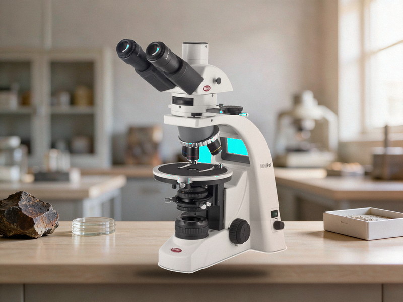
Petrographic Thin Section Scanner Specifications
1. Scanning method and light path
• Tile based stitching rather than a single frame capture
• Transmitted light as standard, with switching between plane polarised and crossed polarised
• Reflected light as an option for opaque minerals, ore phases and polished sections
• Motorised XY stage moving the slide automatically during the scan
• Note: petrographic work needs both light paths, since transmitted only systems cannot show opaque minerals
2. Polarising system
• Polariser and analyser independently rotatable over 360 degrees with 0.5 degree accuracy or better
• Crossed polar extinction position calibratable against a known isotropic sample
• Support for gypsum and mica accessory plates for optic sign and interference order
• Stage or image rotation for extinction angle and cleavage angle measurement
• Note: without a rotatable analyser the extinction angle cannot be measured, losing key identification data
3. Objectives and resolution
• Common magnifications of 2X, 4X, 10X, 20X and 40X, with 4X and 10X most used in petrography
• Strain free objectives are mandatory to avoid false interference colours under crossed polars
• Working distance must clear thin section plus coverslip, especially above 40X
• Numerical aperture and resolution should be stated per magnification for structure and mineral work
• Note: ordinary objectives generate stress birefringence under crossed polars and distort identification
4. Stage and slide compatibility
• Standard thin sections of 46 by 26 mm with 0.03 mm thickness
• Stage travel covering the whole slide with repeatability of 1 micrometre or better
• Support for normal thin sections, impregnated sections and probe sections
• Adjustable slide clamping to avoid cracking or shifting the section
• Note: uneven section thickness causes focus drift across one slide, so flatness should be checked first
5. Stitching accuracy and image quality
• Stitching repositioning error within one pixel or one micrometre
• No visible brightness bands at seams, requiring flat field correction and intensity balancing
• Colour reproduction matching visual observation, since interference colour is identification data
• Z axis autofocus tracking to handle uneven section thickness
• Note: interference colours are measurements rather than decoration, so camera colour management must be calibratable
6. Scanning speed and throughput
• One thin section at 10X within 5 minutes including autofocus and stitching
• 60 to 100 sections per eight hour shift depending on magnification and area
• Batch loading with multi slide magazines and optional automatic feeder
• Live preview during scanning with pause and resume
• Note: throughput figures must state magnification and section area to be comparable
7. Image analysis and quantification
• Grain size statistics including equivalent diameter, aspect ratio, area fraction and size distribution
• Mineral phase area percentage by colour, grey threshold or machine learning classification
• Porosity, fracture density, grain contact and cement type analysis
• Export of raw images with annotation layers for verification
• Note: colour based mineral identification must state accuracy, since 90 and 70 percent are very different
8. Software and data management
• TIFF, JPEG and pyramidal formats with multi level zoom viewing
• Raw data volume per section stated, typically 1 to 5 gigabytes at 10X over a full slide
• Local network multi client viewing with access control
• Database search by sample number, borehole number and depth
• Note: geological samples are archived by borehole and depth, so systems without search are just image piles
9. Where procurement goes wrong
• Transmitted light only, leaving opaque and ore minerals completely unobservable
• Objectives that are not strain free, producing false interference colours that distort results
• Stitching without flat field and intensity balancing, so seams remain and area statistics shift